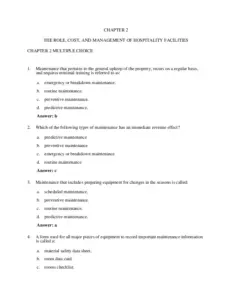
CHAPTER 2
SHORT ANSWER PROBLEMS
2.1 The five elements of the Hierarchy of Process Design are:
(a) Batch or continuous process
(b) Input-output structure of process
(c) Recycle structure of process
(d) General separation structure of process e. Heat-exchanger network/process
energy recovery
2.2 (a) Separate/purify unreacted feed and recycle use when separation is feasible.
(b) Recycle without separation but with purge when separation of unused reactants
is infeasible/uneconomic. Purge is needed to stop build-up of product or inerts.
(c) Recycle without separation or purge product/byproduct must react further
through equilibrium reaction.
2.3 Batch preferred over continuous when: small quantities required, batch-to-batch
accountabilities required, seasonal demand for product or feed stock availability, need
to produce multiple products using the same equipment, very slow reactions, and high
equipment fouling.
2.4 One example is the addition of steam to a catalytic reaction using hydrocarbon feeds.
Examples are given in Appendix B (styrene, acrylic acid.) In the styrene process,
superheated steam is added to provide energy for the desired endothermic reaction
and to force the equilibrium towards styrene product. In the acrylic acid example,
steam is added to the feed of propylene and air to act as thermal ballast (absorb the
heat of reaction and regulate the temperature), and it also serves as an anti-coking
agent that prevents/supresses the coking reactions that deactivate the catalyst.
2-1
2.5 Reasons for purifying a feed material prior to feeding it to a process include:
(a) If the impurity fouls or poisons a catalyst used in the process. e.g., remove trace
sulfur compounds in natural gas prior to sending it to a steam reforming reactor
to produce hydrogen.
(b) If impurities react to form difficult-to-separate or hazardous products/byproducts.
e.g. Production of isocyanates using phosgene. Production of phosgene is
CO + Cl2 → COCl2
The carbon monoxide is formed via steam reforming of CH4 to give CO + H2. H2 must
be removed from CO prior to reaction with Cl2 to form HCl, which is highly corrosive
and causes many problems in the downstream processes.
(c) If the impurity is present in large quantities then it may be better to remove the
impurity rather than having to size all the down stream equipment to handle the
large flow of inert material.
e.g. One example is using oxygen rather than air to fire a combustion or
gasification processes. Removing nitrogen reduces equipment size and makes the
removal of CO2 and H2S much easier because these species are more concentrated.
2-2
PROBLEMS
2.6 IGCC
In modern IGCC plants, coal is partially oxidized (gasified) to produce synthesis gas
CO + H2 and other compounds. Prior to combusting the synthesis gas in a turbine, it
must be “cleaned” or H2S and CO2 (if carbon capture is to be employed.) Both H2S
and CO2 are acid gases that are removed by one of a variety of physical or chemical
absorption schemes. By removing nitrogen from the air, the raw synthesis gas stream
is much smaller making the acid gas removal much easier. In fact, when CO2 removal
is required IGCC is the preferred technology, i.e. the cheapest.
2.7 Ethylebenzene Process
(a) Single pass conversion of benzene
Benzene in reactor feed (stream 3) 226.51
kmo1
h
Benzene in reactor effluent (stream 14) 177.85
kmo1
h
kmol
h 21.5%
X sp 1kmol
226.51
h
177.85
(b) Single pass conversion of ethylene
Ethylene in reactor feed (stream 2) 93.0
kmo1
h
Ethylene in reactor effluent (stream 14) 0.54
kmo1
h
h
kmol
X sp 1 99.4%
h
93.0
kmol
0.54
(c) Overall conversion of benzene
2-3
Benzene entering process (stream 1) 97.0
kmo1
h
Benzene leaving process (stream 15 and 19) 8.38 0.17
kmo1
h
kmol
h 91.2%
X ov 1kmol
97.0
h
8.55
(d) Overall conversion of ethylene
Ethylene entering process (stream 2) 93.0
kmo1
h
Ethylene leaving process (stream 15 and 19) 0.54 0.00
kmo1
h
kmol
h 99.4%
X ov 1kmol
93.0
h
0.54
2.8 Separation of G from reactor effluent may or may not be difficult. (a) If G reacts to
form a heavier (higher molecular weight) compound then separation may be relatively
easy using a flash absorber or distillation and recycle can be achieved easily. (b) If
process is to be viable then G must be separable from the product. If inerts enter with
G or gaseous byproducts are formed then separation of G may not be possible but
recycling with a purge should be tried. In either case the statement is not true.
2-4
2.9 Pharmaceutical products are manufactured using batch process because:
(a) they are usually required in small quantities
(b) batch-to-batch accountability and tracking are required by the Food & Drug
Administration (FDA)
(c) usually standardized equipment is used for many pharmaceutical products and
campaigns are run to produce each product this lends itself to batch operation.
2.10 (a) Single pass conversion of ethylbenzene
Ethylbenzene in reactor feed (stream 7) 223.73
kmo1
h
Ethylbenzene in reactor effluent (stream 10) 102.88
kmo1
h
kmol
h 54.0%
Single pass conversion 1kmol
223.73
h
102.88
(b) Overall conversion of ethylbenzene
Ethylbenzene entering process (stream 1) 121
kmo1
h
Ethylbenzene leaving process (stream 21, 22, 23 & 26) = 0.05 + 0 + 0 + 0.10 =
kmol
0.15
h
kmol
h 99.87%
Overall conversion 1kmol
121
h
0.15
(c) Yield of styrene
Moles of ethylbenzene required to produce styrene (Stream 21) 120.03
Moles of ethylbenzene fed to process (stream 1) 121
kmol
h
Moles of ethylbenzene leaving process (Streams 21 + 26) = 0.15 kmol/h
2-5
kmo1
h
kmol
h
99.3%
Yield
kmol
(121- 0.15)
h
(120.03)
Possible strategies to increase the yield of styrene (not necessary based on the yield
above but these will also increase the single pass conversion) are:
(i)
Increase steam content of reactor feed this pushes the desired equilibrium
reaction to the right.
(ii) Increasing the temperature also pushes the equilibrium to right but increases
benzene and toluene production.
(iii) Remove hydrogen in effluent from each reactor this will push the equilibrium of
the desired reaction to the right and reduce the production of toluene from the
third reaction. This will require the use of a membrane separator, shown in the
following diagram.
Reactor, R-401
E-402
H2 rich stream
Membrane
Separator
ethylene
Reactor, R-402
2-6
2.11 Route 1: 2A → S + R
Key features are that no light components (non-condensables) are formed and only
one reactant is used. Therefore, separation of A, R, and S can take place using
distillation columns.
Route 2: A + H2 → S + CH4
Unlike Route 1, this process route requires separation of the non-condensables from
A and S. If hydrogen is used in great excess (as with the toluene HDA process), then
a recycle and purge of the light gas stream will be required. Otherwise, if hydrogen
conversion is high, the unreacted hydrogen along with the methane may be vented
directly to fuel gas.
Route 1 PFD sketch
Route 2 PFD sketch gas recycle shown dotted since it is only needed if H 2 is used in
(considerable) excess and must be recycled.
Route 1 is better since:
2-7
Simpler PFD
No gas recycle (no recycle compressor)
No buildup of inerts (CH4) so recycle stream is not as large
All products are valuable fuel gas in Route 2 has a low value
2.12
(a) Good when product(s) and reactant(s) are easily separated and purified (most
often by distillation.) Any inerts in the feed or byproducts can be removed by
some unit operation and thus recycle does not require a purge.
(b) When unused reactant(s) and product(s) are not easily separated (for example
when both are low boiling point gases) and single pass conversion of reactant is
low.
(c) This is only possible when no significant inerts are present and any byproducts
formed will react further or can reach equilibrium.
2-8
2.13
(a)
Order of volatility is acetaldehyde, water, ethyl acetate, ethanol, isobutanol, acetic acid.
(b)
Alternative 1 assumes butanol and acetic acid can be sold as a mixed product ⇒ very
unlikely so probably have to add another column to separate.
2-9
This alternative recycles C2H5OH and produces “pure” acetaldehyde the remaining
streams are considered waste incineration of organics or wastewater treatment are
possible ways to remove organics.
2-10
2.14
A and R are both condensable and may be separated via distillation
Treat remaining gas stream in a water absorber to remove product C
C may be separated by absorption into water
R will be absorbed into water
G and S cannot be separated except at very high pressure or low temperature
After reaction, cool and condense A and R from other components.
Separate A from R using distillation and recycle purified liquid A to the front
end of the process
Separate C and from water via distillation
Recycle unused G containing S since S does not react further. But a purge must
be added to prevent accumulation of S in the system. This stream must be
recycled as a gas using a recycle gas compressor.
If the value of G was very low, then consider not recycling G (and S.)
2-11
2.15
Malt Whiskey Process
Grain Whisky Process
2-12